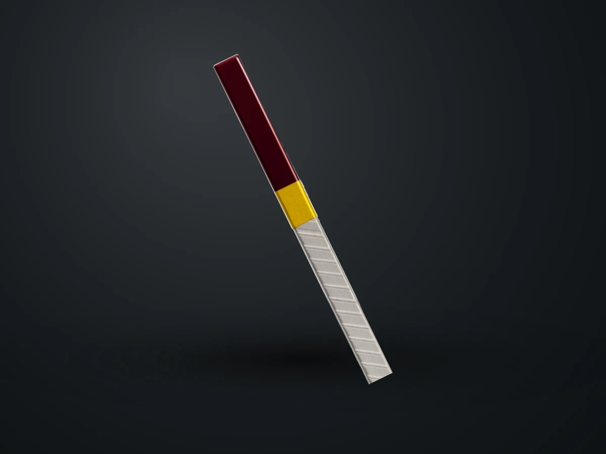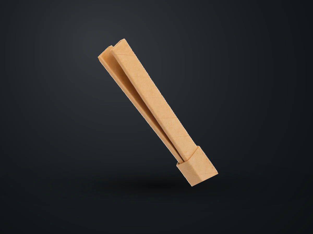
Using a single large-section conductor in high-current windings is problematic for two reasons: it is hard to wind and its effective section drops under alternating current. The common solution is to split the section into several thin conductors. But this solution brings its own problem.
Why Parallel Conductors?
Alternating current does not spread evenly over the whole conductor. The skin effect pushes the current toward the outer surface of the conductor; the proximity effect further distorts the current distribution under the influence of neighbouring conductors and the leakage flux. As the section grows, the middle of the conductor becomes practically unusable. Using a bundle of thin conductors limits this loss; moreover, bending is much easier during winding.
The Resulting Problem: Circulating Currents
Parallel branches are located at different positions within the winding. Since the leakage flux is not distributed evenly along the winding, the amount of flux each branch is linked to differs; this creates small voltage differences between the branches. Because the branches are connected to each other at both ends, this voltage difference produces a circulating current over a closed circuit. This current contributes nothing to the load, it only produces heat.
The result is a higher-than-expected load loss and local overheating in some branches. In a significant portion of designs whose losses are calculated on paper but cannot be met in measurement, the problem is here.
The Solution: Transposition
Transposition is the change of position of the parallel branches along the winding. A branch is on the outermost side in one part of the winding and on the innermost side in another. Thus the total flux linkage each branch sees is equalised, and the voltage difference between branches — and therefore the circulating current — is largely eliminated.
Three approaches are seen in practice:
| Arrangement | Number of branches | Circulating-current risk | Typical application |
|---|---|---|---|
| Single conductor | 1 | None | Small and medium-section windings |
| Twin conductor | 2 | Low; removed by simple transposition | Motor and medium-power transformer windings |
| Triple conductor | 3 | Medium; planned transposition needed | High-current low-voltage windings |
| Continuously transposed conductor (CTC) | Many | Very low; transposition is done within the conductor | Large power transformers |
The Relation of Eddy-Current Loss to Size
The second benefit of splitting into parallel branches is in eddy-current losses. The loss caused by the eddy currents the leakage flux induces within the conductor rises with the square of the conductor dimension perpendicular to the flux and with the square of the frequency. This relationship sets the direction of the design: keeping the section the same but thinning the conductor in the flux direction markedly lowers the loss. This is the real logic behind preferring twin and triple arrangements.
Is Transposition Enough on Its Own?
Transposition largely suppresses circulating currents; but if the leakage-flux distribution within the winding is not homogeneous, full balance cannot always be achieved. Especially at the winding ends the flux changes direction and the axial component becomes pronounced. In these regions the eddy losses come out higher than in the middle of the winding; the result is a local temperature rise at the ends.
Transposition is therefore handled not on its own, but together with shields that steer the leakage flux, the position of the cooling channels and the conductor sizing at the winding ends. In some designs, using a thinner conductor at the end regions is the practical way to balance the loss distribution.
Verifying the results is done by measurement. In a load-loss measurement, a value coming out markedly higher than the calculated value usually points to circulating currents that have not been eliminated. Seeing higher-than-expected heating in certain regions of the winding in a temperature-rise test supports the same finding.
Application Notes
- Branch insulation: The parallel branches must be insulated from each other; otherwise transposition has no meaning.
- Transposition points: The change of position must be planned at balanced intervals along the winding; randomly made transitions can increase the imbalance.
- Mechanical continuity: No gap should form between conductors at the transition regions; winding tightness must be preserved.
- End connections: All branches must be connected at the same point and so as to see equal resistance.
In the supply of twin and triple conductor, the number of branches, inter-branch insulation and total section are defined together. If you share your winding geometry, we can assess the suitable arrangement together.
Summary
- Splitting a large section into parallel thin conductors limits the losses arising from skin and proximity effects.
- When parallel branches see different flux linkage, a circulating current arises between them; this current contributes nothing to the load, it only produces heat.
- Transposition removes this imbalance by changing the position of the branches along the winding.
- Because eddy loss rises with the square of the conductor dimension perpendicular to the flux, thin multi-conductor arrangements are advantageous.
- Inter-branch insulation, balanced transition points and equal end connections are indispensable conditions of the application.